Bit Tray Basics Quick Start Guide
1. What's in the Box

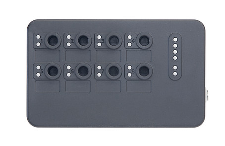
Wireless Bit Tray
Controller Interface Module (PCM DIO)
USB-C Charging Cable
Wire Harness
(Custom or Controller Specific)
Screwdriver & Accessories
2. Overview

The wireless bit tray system enables all of the benefits of a traditional bit tray, without the cords that limit its mobility. A digital input and output module (DIO) is connected to the controller's 24V accessory terminals, maintaining wireless communication to the bit tray.
The bit tray uses a rechargeable 3.1Ahr li-ion battery, with a USB-C charge port, operating for multiple shifts on a single charge. LEDs are used to indicate not only the commanded bit (socket select mode), but also the status of each bit presence sensor, eliminating any issues if debris blocks the bit from fully seating.
Accessory kits are included to enable an easy installation to standard controllers.
3. LED Indicators - DIO

Lower row of 8 - Green
-
Bit Presence indicator
-
Will be blue if a bit is sensed.
Power Indication - Red when on
Upper row of 8 - Blue
-
Triggered by the outputs
of the controller
-
#1 is the left. #8 is far right.
Communication Status
-
Blue = on & not connected to bit tray
-
Green = on & connected to bit tray
-
Red = Lost connection with bit tray
LED Indicators - Bit Tray
1
2
3
4

Green
Bit Commanded
Indication
(when used with
Socket Select)
Communication Status
-
Blue = on, not connected to DIO
-
Green = on & connected to DIO
-
Yellow flashing = low battery
-
Red = lost connection
Charging Status
-
Blue = charging
-
Green = fully charged
Charge Status
-
All 4 Green = fully charged
Blue
On when bit
is present
5
6
7
8

Communication LEDs should always match each other.
Bit commanded and present indicators should always match each other. If the torque tool has an error code, these indicators make it easy to understand if the issue is with the controller, or with the bit tray system.

4. Bit Tray System LEDs
Status LEDs should always match
5. How To Charge
Any USB charger can be used with the supplied cable to charge the bit tray.
The Ingersoll Rand QX battery charger is equipped with a USB output that can be used to charge the bit tray
USB-C to bit tray can be installed in either orientation

