Bit Tray Installation Wiring & Installment
Ingersoll Rand PCM for QX Tools
Pico MES Components:
-
Digital IO Module
-
Wire harness
-
Small Screwdriver
Ingersoll Rand PCM
Requirements
Ingersoll Rand Components:
-
PCM with Antenna
-
5V power supply (for PCM) - upper power supply
-
24V power supply (for DIO) - lower left
A wiring diagram and mechanical prints can be downloaded with the buttons below:

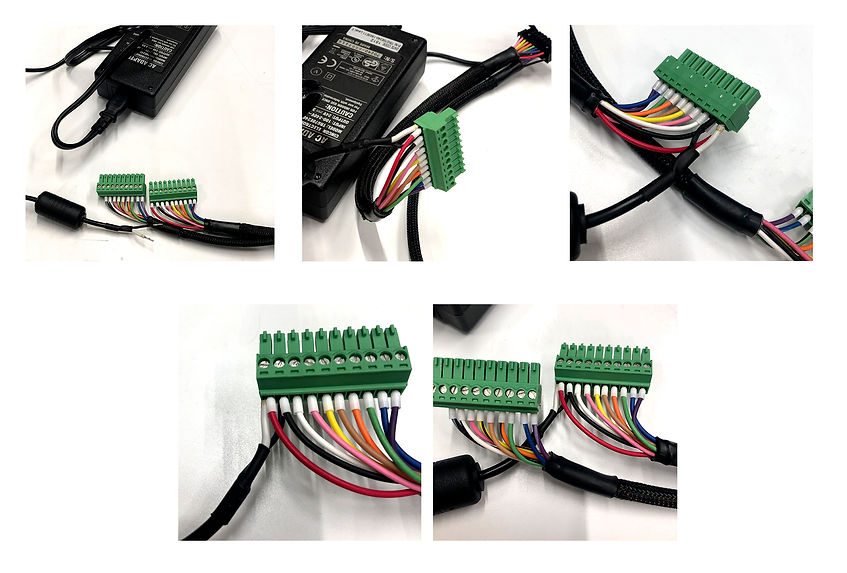
24V Power Supply to Harness Connections
The DIO portion of the wireless bit tray system will be powered by the 24V power supply that comes with the IR PCM system. It has two soldered wire leads, one white (+24V) and one black (0V). These will be installed into the screw terminal connector in the same location as the red and black wires.
-
Use the small screwdriver provided to loosen the terminals on the connector.
-
Install the white wire into position 1 of the connector with the red wire from the harness.
-
Install the black wire into position 2 of the connector with the black wire from the harness.
-
Use the screwdriver to tighten the terminals
-
If these are reversed, the DIO will not function so pay attention on this step.

1. Install 24V Power Supply to Harness
PCM Connections

2. Route the 5V Power Supply Wires
Route the 5V power supply wires through the cavity, under the area where the connectors will be installed. This will help to position the choke on the 5V power supply in the least annoying spot after the rest of the wiring is installed
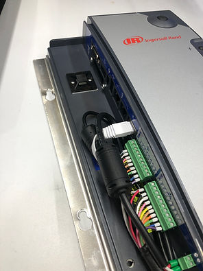
Install the first connector (solid color wires, all 10 cavities filled, with power supply) to the outputs block of the PCM (lower connector). We like to route the 24V power supply wires up the PCM cavity, as the choke on the wires is most out of the way in this orientation. We then route the power wire back under the connectors and out of the PCM cavity. Seems to put the choke in the least annoying position.
3. Install Harness & 24V Power Supply

Install the second connector (striped wires, 9 cavities filled) to the inputs block of the PCM (upper connector). Be careful with the wires around the ground stud, ensuring they are not damaged. Both power supply wires should now be trapped under the connectors and inside of the ground stud.
4. Install the 2nd Connector

If you are communicating with your PCM via an ethernet connection, now is the time to install the cable. We like the flat Cat6 cables for these applications, as they route easily and don’t take up much space. They are readily available in various lengths on amazon (search “flat cat6 cable”). If you don’t communicate with your PCM for control or datalogging, YOU SHOULD! It’s easy to do...
5. Install the Ethernet Cable

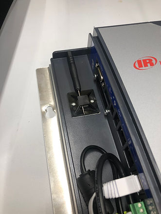
In this step, you’re going to route the 5V power supply cable, so you can remove the excess wire back from the cavity, before closing the zip tie. Bend the cable back towards the PCM connection and install the 2-way screw terminal connector. Pull the excess wire from the cavity.
6. Initial routing of 5V cable

You can remove the 5V connector to give a bit of room if desired. Bunch up the cables (5V power supply, 24V power supply, the Pico MES harness, and the ethernet cable if used), and cinch the zip tie to secure the wiring. You can then use a set of flush cuts to remove the tail of the zip tie.
7. Zip Tie Time

Reinstall the 5V power supply connector to the PCM. There’s plenty of room for the choke to live above the inputs connector, over the ground stud. Gently bend the wires until it rests generally above them. One quick check for clearances and then you’re ready for the cover.
8. 5V Power Supply Final Install &
Prep for Cover

-
It can be difficult to remember to have a small screwdriver onhand, and it is really annoying to have to walk across a plant to go get one to change a PCM DIO connection or swap power supplies. It might be helpful to leave the one that comes in the bit tray kit in the zip tie block, as long as you check for this when installing the block. Large wall arrays could have 6-8 PCMs on one rack, which means there’s a fighting chance that 1 of the 6-8 screwdrivers left in the zip tie block would be present, and not “borrowed” to never be returned. Also, a hidden set of flush cuts is a good idea..
Tips and Tricks

-
An adhesive backed zip tie block (like McMaster 7582K11) in the PCM is helpful. They are cheap and easy, and the cover tends to mean they’re not exposed to the environment so the adhesive lasts for quite a while (use IPA to clean the surface before installation!)
-
When PCMs are wall mounted, it can be useful to use 8020 brand 25-series extrusions, and velcro the power supplies to the back of the controllers, creating a very clean install. Then use the zip tie block in the PCM cavity to secure the excess wires from the power supplies (instead of then hanging or being bundled on the wall).

-
Install the cover to the PCM by guiding the upper portion over the catch on the top, then guiding it down until the front seats. It should install very easily and not want to pop back off. If it doesn’t do that, verify you’re not crushing a wire or component.
-
You can then secure the cover with the captured flathead screw in the lower area of the cover.
9. Cover Install

-
You can now install the DIO by making the single connection. Simply line up the connector with the tang up, and push until it is fully secured. If desired, you can use a T8 torx drive tool to remove the 4 screws that secure the DIO cover to make it easier. Removing the connector requires releasing that tang on the top of the connector, then wiggling it out until the friction from the terminals is released. This is much easier with the cover off. Just be careful not to touch the PCBA in the enclosure, to avoid any static discharge related issue.
10. Connect the DIO

The DIO comes with 2 mounting ears for M6 or ¼-20 screws to secure it. Button head cap screws are nice, but you can choose based on your preference. The harness is long enough for two position of the DIO relative to the PCM.
-
Under the PCM: Simply secure the PCM to the DIO
-
On the PCM: A custom purchasable bracket is coming that will allow the securing of the DIO to the PCM via the lower two PCM mounting points. For now, Velcro works well, as long as you’re indoors / not exposed to high humidity or chemicals that can cause the adhesive on the velcro to fail.
Custom harness are possible (contact@picoMES.com) or see the base info page for all of the connector and terminal PNs if you are skilled at wiring and want to make your own.
11. Mount the DIO


The rocker switch on the DIO is used as an on/off switch, removing power from the unit when desired. Once the 24v power supply is plugged in, cycling this switch will cause the power indication LED (lower left of the lid) to come on. Red means it has power, off means it does not.
12. On / Off Switch

There are two primary ways bit trays are typically used:
1. Socket Select Method:
This setup is basically when you have either an MES or a PCM drive the bit to be used, based on which pset is being commanded at the time. Typically this is used when a fixed sequence or order of psets are going to used. So each pset would have a bit assigned to it, and require only that bit to be removed from the tray in order to enable the torque tool.
2. Configuration (aka Pset) Select Method:
This setup is when the operator is going to drive the pset to be used, based on which bit they choose to select at a given moment. There is no control over the sequence/order of pset usage from the controller. Each position of the bit tray will have a pset assigned to it in the controller. Select bit 1, and the controller will send the desired pset to the tool, and so on.